Setting Up the CO2 Tank
Finding a Liquid CO2 Tank
You will need a liquid CO2 tank with a siphon tube–this is a specific, but standard gas tank that most liquefied gas companies (for example, Airgas, Air Liquide, BOC Gas, etc.) will carry but you must mention you need a siphon tube. A normal CO2 gas tank will not work because it cannot deliver liquid into the manuclave without the siphon.
You can also try contacting a local welding supply company or a beverage supply company who often will refill and rent liquid CO2 tanks as well.
Make sure your tank has a CGA320 fitting (standard in the United States). If you are working in a country with different gas tank standards, you will have to adapt the design and parts accordingly.
A small gas tank (about 2.5 ft. tall) is called a “20-pound” tank (because it holds 20 pounds of liquid CO2) but actually weighs about 45 lbs. A standard gas cylinder (stands stands about 5 ft. tall) is called a “50-pound” tank (holds 50 pounds of liquid CO2) and weighs about 150 lbs. Depending on where you’re working (a basement vs. a lab, for example) you will want to select your tank accordingly (i.e., make sure you can move it to where you need to use it!).
Connecting the Liquid CO2 Tank
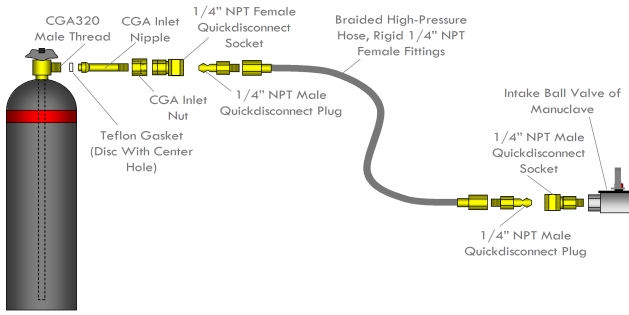
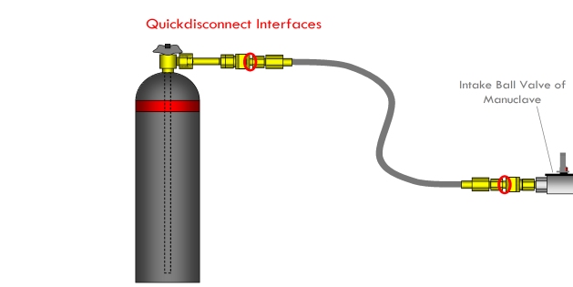
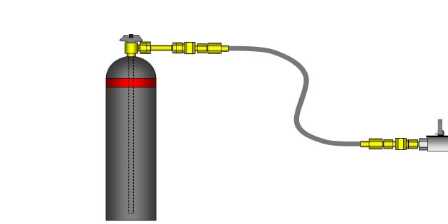
The diagrams below show how all of the fittings connect together. Make sure all NPT threads are sealed with pipe thread tape.
Assembling the NPT Pipe Fittings
(These instructions are a little different than the ones given in the Parts and Schematics article)
Looking face-on down the length of a male-threaded pipe fitting, take the pipe thread tape and start to wind it clockwise around the thread. Make sure all of the threads near the edge are covered. Wrap two to three layers around the entire thread. Now, insert the fitting into the female mating connector and screw it in as far as you can with your fingers. Finally, take a wrench and screw it in as far as you can with the wrench. This should provide a suitable high-pressure seal.
Remember to use torque to your advantage—use a long wrench and apply force at the end of the wrench.
It’s best to use an adjustable crescent wrench or fitted crescent wrench set instead of a pipe wrench (which has teeth) for assembling pipe fittings so you don’t damage the pipe fittings in gripping them, but ifyou need to use a pipe wrench to get the job done then fine.
Tips and precautions:
- Don’t use thread sealing compounds, they really don’t hold at high pressures
- Don’t try to epoxy or glue fittings together
- Don’t try have fittings welded together here
- Make sure to clean the threads and pipe thread tape of any detritus before wrapping
- If a fitting doesn’t seem to be threading right, don’t force it or you will strip the threads and make the fitting useless—this is especially important with brass fittings
The CGA Inlet Nut and Nipple
These two components work together to convert the CGA320 fitting on the liquid COKsub>2 tank to a 1/4″ NPT male thread. First, a Teflon gasket ( a Teflon disc with a hole in the center) is placed on the face of the CGA fitting on the tank. Be sure to ask for a couple of these from the company you get the gas tank from. Next, slide the inlet nipple through the inlet nut. Lastly, tighten the inlet onto the CGA fitting on the gas tank. It will compress the nipple onto the Teflon gasket onto the CGA fitting. You may or may not need to use pipe thread tape on the CGA fitting to get a good seal.
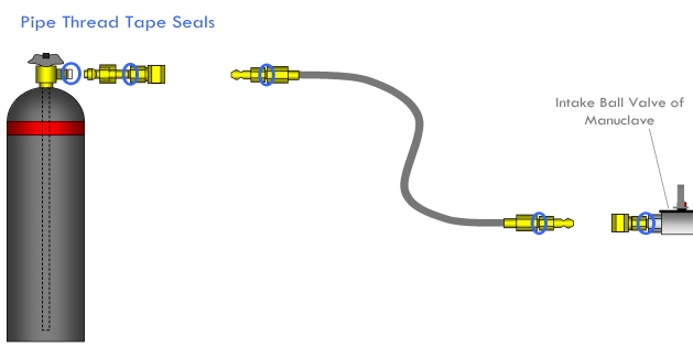
All NPT fittings should be sealed with pipe thread tape. The CGA outlet on the gas tank can also be wrapped with pipe thread tape.
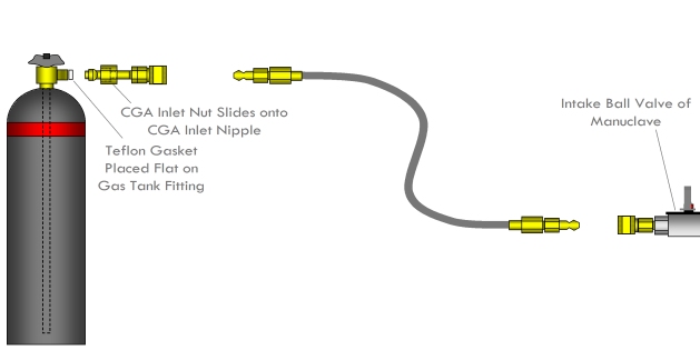
The CGA inlet nut slides onto the CGA inlet nipple. The Teflon gasket is placed flat on the CGA outlet on the gas tank.
The Quickdisconnect Fittings
Once assembled, the hose can be quickly connected or disconnected from both the gas tank and the manuclave. The quickdisconnects work by pulling back on the spring-loaded collar on the socket and inserting or removing the plug into it and then releasing the socket collar to lock the fittings.
WARNING: Never try to connect or disconnect the quickdisconnects while anything is pressurized

